MOTOR CONTROL - BRUSHLESS DC (BLDC)...
MOTOR CONTROL - BRUSHLESS DC (BLDC) MOTOR

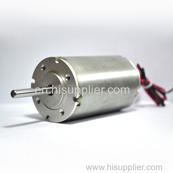
The brushless DC (BLDC) motor can be imagined as the opposite of the brush DC motor, in which the permanent magnetism is on the rotor and the wire is wound on the stator. Therefore, the motor has no brushes and commutator, which eliminates the disadvantage associated with the sparks produced by the brush DC motor.
We call it DC motor because its coil is driven by DC power, and the DC power is applied to different stator coils in a predetermined order. This process is called commutation. However, BLDC is not appropriate, because the motor actually belongs to the AC motor. During the circuit cycle, the current in each coil alternates between positive and negative. The stator is generally a convex structure, which aims to produce a trapezoid back EMF waveform, which is in accordance with the applied commutation voltage as much as possible.
Another misunderstanding of the BLDC motor is about how it is driven. The stator coil, which is driven by the open loop step application, determines the rotor position. In the BLDC motor, the rotor position determines which stator is to be driven. The stator flux vector position must be synchronized with the rotor flux vector position (rather than the opposite) to make the motor operation smooth. To achieve this goal, it is necessary to understand the rotor position to determine the stator coils to be driven. There are many techniques available for this purpose, but the most common technique is to monitor the rotor position using the Hall effect sensor. Unfortunately, these sensors and their associated connectors and wiring harnesses will increase the cost of the system and reduce the reliability.
In order to reduce these problems, a variety of technologies have been developed to eliminate these sensors and achieve sensorless operation. Most of the techniques rely on the rotation of the motor to extract position information from the back EMF waveform around the stator. However, the technology of back EMF sensing is useless when the motor rotates slowly or statically, because the back EMF waveform is very weak or does not exist at all. Therefore, we have been developing new technologies to get the rotor position information from other signals at low speed or zero speed.
Previous:
DeepMind explores inner workin
Next:
How to Determine the Power Rat


